• Hello Guest, welcome to the initial stages of our new platform!
    You can find some additional information about where we are in the process of migrating the board and setting up our new software here

    Thank you for being a part of our community!

tfrasca's 142 Turbo Project

just invent a variable length intake manifold a-la the old SHO's.

I'll also make a variable width brake booster to make room for the runners when they're longer.

If you want to go down a deeper rabbit hole, check out the Induction article at Grape Ape Racing. Build some spreadsheets, and go to town. If you understand the assumptions made, and Helmholtz resonators, you can make some pretty accurate intakes.

https://grapeaperacing.weebly.com/technical-articles.html

Oof. I'll check that stuff out, but I want to get this thing done some time in 2020. I tend to get overwhelmed and do nothing when I learn about the correct way to do things...
 
Re: the curved runners, that's how I got decent runner lengths on my 8 valve manifold. Plenum was up above the ports, and it worked well since I didn't need room for injectors and fuel rail on the manifold (they were in the head). Now I'll need to make room for injectors in the manifold, so moving the plenum up and toward the head (away from the booster) is a trickier proposition.

The runners are admittedly on the short side with the Cosworth design, and those curve DOWN slightly, which adds maybe 10-15mm to the length. If I tried to recreate it with straight runners, the distance from velocity stack to flange would probably be 6" or less.

I went way down the rabbit hole on intake runner length last time, and I think I was able find a decent compromise with the last manifold. This time, with less room, I will need to make concessions. The plus side about shorter runners, is that I wouldn't mind revving this thing out. 8k with lighter pistons and rods seems reasonable, and my new turbine housing should flow up there. So maybe if the manifold ends up with short runners, I look at some cams and fueling to support a higher revving, less-of-a-torque-monster engine.

Sweet, sounds like you have it under control. Guess I didn't realize that you had done curved runners on the 8v manifold but I see that now. I've been playing with runner length calculators which is why I asked. Although I'm working with a tiny 1.1L Opel engine that has siamesed intake ports so only 2 openings in the head. I think in that case I want approximately 1/2 of whatever runner length I'd choose for conventional separate ports, which is convenient, but I need to verify this assumption.

I tend to get overwhelmed and do nothing when I learn about the correct way to do things...

I know the feeling - at some point you have to decide that you know enough and just move forward with the task at hand...it's tough sometimes though!
 
Sweet, sounds like you have it under control. Guess I didn't realize that you had done curved runners on the 8v manifold but I see that now. I've been playing with runner length calculators which is why I asked. Although I'm working with a tiny 1.1L Opel engine that has siamesed intake ports so only 2 openings in the head. I think in that case I want approximately 1/2 of whatever runner length I'd choose for conventional separate ports, which is convenient, but I need to verify this assumption.


I know the feeling - at some point you have to decide that you know enough and just move forward with the task at hand...it's tough sometimes though!

I do have a basic understanding of plenum size, runner lengths, etc. But the consensus is that all of it matters a fair bit less on a forced induction engine, right? Trying to tune a runner for velocity and maybe pulse resonance is key for N/A engines, but the turbo is just going to jam that air in there. Or is that what people tell themselves so they can ignore the facts?

Also, as far as my intake goes, what are people's thoughts on putting the injectors at the bottom of the runners. Sure, they wouldn't be pointing right at the tops of the valves, but if you came in at a shallow angle, the spray would still be going right down the throat of the port. If I did injectors on the bottom, it would open up a bunch of design constraints.
 
There’s not a lot of information out there about boosted resonance tuning. I was able to fine a couple fsae papers on it, but there was not a whole lot of support data. For my intake/exhaust mani I decided that 4th-5th wave was going to be achievable, and I made it so that if needed I can add spacers quickly on the dyno.
 
There?s not a lot of information out there about boosted resonance tuning. I was able to fine a couple fsae papers on it, but there was not a whole lot of support data. For my intake/exhaust mani I decided that 4th-5th wave was going to be achievable, and I made it so that if needed I can add spacers quickly on the dyno.

Can your intake and peak rpm also take advantage of the higher order reflections? I found that higher order reflections can be beneficial as you end up with more reflective nodes over a broader RPM range. So the area under the curve increases, instead of just one spike.

If an intake is tuned to lower reflective orders (let's say 1-3), then there will be a larger "boost" available, but there will also be an equally as large negative effect as well at an rpm higher and lower.

To address your question on boosted applications, you change the speed of sound as well as the air-density (well, the change in density changes the speed of sound in air). This requires the plenum to be slightly larger than a NA one.... If you wanted the same resonance frequency and reflection orders.

So my 4-5th wave was pulled from the 6000rpm mark, and probably gets in to the 7-8th around the top of the torque curve at 3500... But I have no idea how the new pturbo is going to play with it. the 15g I was running was an insta boost deal on this engine. Id hit 18-20psi around the 2500-3k mark depending on gear. This new stuff is going to be way different. looking at the numbers the "ideal" setup for me, and actually requires me to run a 1" spacer between plenum velocity stacks and the runners underneath. I've designed my runners to flanged with DCOE flanges so I can just buy off the shelf spacers.

For plenum volumes, I was looking over a few different papers that had some good data, and I settled on approximately 150% of total displacement. It seemd like this was the most frequently agreed upon number.
 
What do you guys think about putting the injectors on the bottom of the runner? That's the only way I'm going to be able to think about different runner lengths, but it feels weird to be spraying fuel up onto the roof of the port instead of down onto the valve.

Without looking at anything, that doesn't seem to be the best option.

Could you have the plenum lower/below the ports? You probably couldn't run a TB in the same location you did on the 8v, could you run the TB in the center of the plenum (possibly angled slightly down)?

Lots of different Audi intakes here: https://www.bufkinengineering.com/intake manifolds.htm

Something like this, but the injectors on top: https://grabcad.com/library/audi-gruppe-b-20v-intake

large.jpg

For the plenum to go below the runners, they'd have to curve down pretty sharply right out of the head. Doesn't seem great. TB in the center of the plenum is tough because that's right where the booster is. I was thinking about a kind of split plenum setup, like the one you linked here, but that still doesn't allow for longer runners.
 
For the plenum to go below the runners, they'd have to curve down pretty sharply right out of the head. Doesn't seem great. TB in the center of the plenum is tough because that's right where the booster is. I was thinking about a kind of split plenum setup, like the one you linked here, but that still doesn't allow for longer runners.

The runners coming out the head wouldn't need to have much of a bend (significantly less than the picture I posted). Then just offset the plenum to be low enough to clear the injector bodies.

Or, what about a copy of the Cosworth manifold, but slightly shorter runners?
Make the plenum slightly larger, and move the TB to a spot where it fits?
You could even use the stock manifold flange and injector bungs to make it easier.

The copy of the Cosworth is the plan, but I was brainstorming ways to get the runners longer. I think they'll be on the short side for the engine (based on an educated guess, not actual math). I would use the Volvo flange and injector bungs, but the angle is much shallower than the Cosworth bungs, and with the short runners, you really want to get the fuel rail up and out of the way of the base of the plenum.

The problem with offsetting the plenum down, is that the velocity stacks that I want inside the plenum would interfere.
 
Got ya.

I don't think the length of the runners are that big of a deal on your setup. The 8v and 16v heads have pretty long ports in the head, so they're a bit misleading. The shorter a runner is, the more constructive wave harmonics you will get. Instead of it being waves 2-3, you can get 5-10. The waves will be lower strength, but you get them spread out over a larger RPM spread.

For instance, a TT500 yamaha race motorcycle engine has the broadest powerband with a complete intake track length of ~150mm (valve to end of carb velocity stack). Going longer kills the power everywhere until you get to adding about another 6", then you get a higher peak HP but lower area under the curve.
CRF450 Hondas like ~100mm intake length, but that's with a 12.5k redline.
Those are the only engines that I have spent a significant amount of time dyno tuning and testing.
 
Also, this kind of all goes out the window when you add boost.

That is what I'm banking on. All this is just for my own education, and I'll attempt to understand it, but what I do know is that I have a big old turbo strapped to the other side of the engine. More bench racing as far as THAT manifold is concerned later.
 
I do have a basic understanding of plenum size, runner lengths, etc. But the consensus is that all of it matters a fair bit less on a forced induction engine, right? Trying to tune a runner for velocity and maybe pulse resonance is key for N/A engines, but the turbo is just going to jam that air in there. Or is that what people tell themselves so they can ignore the facts?

It's mostly the latter. The physics don't change just because air density, flow, and pressure are higher. Forced induction will more than make up for deficiencies elsewhere though if your goal isn't to extract every last drop of power from a given engine. I think people tell themselves "all that NA tuning stuff doesn't matter" because after bolting a turbo on, they're able to hit their power targets without any of that business.

Can your intake and peak rpm also take advantage of the higher order reflections? I found that higher order reflections can be beneficial as you end up with more reflective nodes over a broader RPM range. So the area under the curve increases, instead of just one spike.

If an intake is tuned to lower reflective orders (let's say 1-3), then there will be a larger "boost" available, but there will also be an equally as large negative effect as well at an rpm higher and lower.

To address your question on boosted applications, you change the speed of sound as well as the air-density (well, the change in density changes the speed of sound in air). This requires the plenum to be slightly larger than a NA one.... If you wanted the same resonance frequency and reflection orders.

Higher order tuning is certainly interesting; I'll look into that more too...

There’s not a lot of information out there about boosted resonance tuning. I was able to fine a couple fsae papers on it, but there was not a whole lot of support data. For my intake/exhaust mani I decided that 4th-5th wave was going to be achievable, and I made it so that if needed I can add spacers quickly on the dyno.

Also, this kind of all goes out the window when you add boost.

If you look at all of the purpose-built boosted racing engines out there now you'll notice they look like highly tuned NA engines, but with the addition of a turbo. The optimum lengths and volumes change because of boost but the concepts are the same.

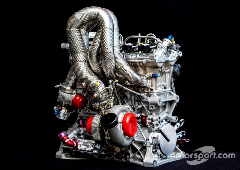
Since Audi & BMW released glossy photos of their new DTM engines we can look at this and talk about it...700hp reliably from a 2.0L four. Although Audi didn't show the intake manifold, look at the exhaust - they wouldn't have gone to all that trouble of designing and packaging a tuned 4-2-1 long tube header if it didn't matter at all...

audi-2-0-tfsi-dtm-2019-engine-1.jpg


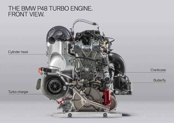
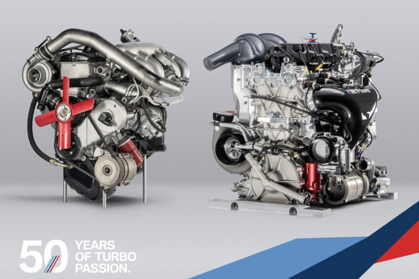
BMW did release images of their full DTM engine including intake manifold. They had to package the throttle body low & tight down next to the crankcase, and there's a long transition to the plenum, but it's impossible to see what the actual internal runners or trumpets look like from these photos. They likely keep the runners short though as this is a high-revving racing only application.

P90346498-bmw-p48-turbo-engine-600px.jpg


BMW-Motorsport-P48-Engine-16-of-23-830x553.jpg
 
Duder- that was why I decided on my design (it’s in the recent page of the build thread) mid length 4-2 twin scroll header, 14.75” near equal length +/- .25” to merge, then the intake is right around 11.75 total length with enough room to decrease to 10” or increase to 13”. Looking at Indy car stuff and seeing how most designers have come pretty close to equal volume on either side of the turbo system, and some of the things gathered from people I’ve met through work as well as picking your brain some, I feel like I should see benefits in low-mid-high rpm as well as significant gains in transient response. Basically I’m shooting to get net volume from valve to wheel as close to equal as possible in order to maintain high efficiency of transient response, if that makes any sense.
 
Culberro summarized it nicely to me: Those things still matter, but 2 psi of pressure at the back of the intake valve means a whole lot more in a naturally aspirated motor than it does in a turbocharged one that already has 20. The difference is 200% in an NA car, but maybe 10% in a largely similar turbo engine, to grossly generalize for the sake of driving the point across. In DTM you care about getting that little bit of extra powerband and less thermal loading at the cost of packaging and serviceability; that is to say the DTM car gets taken apart every week whereas a street driven 700 hp RS7 with air conditioning, ULEV emissions, the expectation of going for at least 100,000 miles before even having to glance at the turbos and silent operation, uses a much bigger engine with the exhaust manifolds molded into the cylinder head. Its all in the application and its associated restrictions.
 
Back
Top