• Hello Guest, welcome to the initial stages of our new platform!
    You can find some additional information about where we are in the process of migrating the board and setting up our new software here

    Thank you for being a part of our community!

740 Fuel gauge sender wires

itlksez

Member
Joined
Oct 6, 2009
Location
Post Falls, ID
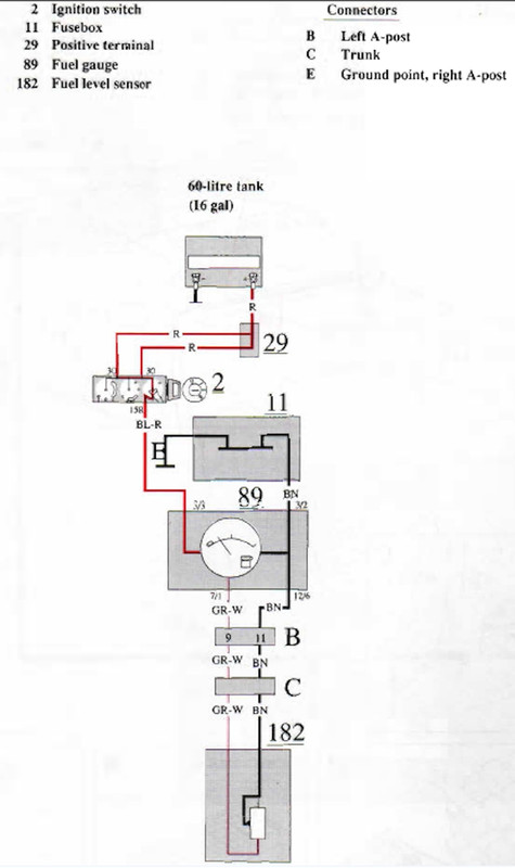
I have two wires coming from my sender. One is brown, the other is white/gray. Both show 100% resistance (tester doesn?t move) when tested to (-) independently, and they show zero resistance (gauge spikes) when tested between the wires. Tank is around 1/2 full.

The gauge I got only needs one wire. What are these two wires?

I?m reading that the brown should be grounded? If I ground the brown, I still show no resistance in the gray wire. Is my sending unit screwed up?
 
What year is your car? Many years of these have two or three wires because there is a transfer fuel pump in there along with the float for the fuel gauge. One wire is the pump power. The other is fuel level. On some models there is a ground wire, too. The wire that has 12v on it when the car is running is the pump power feed.

One of the guys who knows the color codes better than me will chime in.
 
Last edited:
What year is your car? Many years of these have two or three wires because there is a transfer fuel pump in there along with the float for the fuel gauge. One wire is the pump power. The other is fuel level. On some models there is a ground wire, too. The wire that has 12v on it when the car is running is the pump power feed.

One of the guys who knows the color codes better than me will chime in.

I’m 99% sure it’s an ‘87.
It has four wires coming out of the top of the sender. Black is ground, purple is for the pump. The other two are in question.
 
One is brown, the other is white/gray.

Black is ground, purple is for the pump. The other two are in question.

Ignition switch sends power to the gauge over red/black.

Gauge grounds part of itself using brown, going back to the fuse box bus bar.

The "activation" part of the gauge makes a loop through the sender via gray/white on the way out, and brown on the way back, then to ground via the gauge's brown.

The gauge I got only needs one wire.
*IF* it's compatible with the sender, you'd just connect it to power (red/black), and signal (gray/white), and assume the brown will still be grounded.

Older single-wire gauges used full current to heat a bi-metal strip inside the gauge to move the needle (well, pulsing current... 12v on-off-on-off gave a 5v average), and assumed the sender was calibrated for it, and robust enough to take the current.

I believe our gauges are a "double coil moving-iron" style, where one coil creates a small fixed magnetic field, the other coil is arranged at 90 degrees from the first, and the small current through the sender varies the strength of the second coil's magnetic field. The difference in the two fields is what positions the needle. More accurate, and isn't affected by voltage variations.

I don't know how much current your gauge requires, or how much your sender can tolerate before it burns out. I guess you'll have to try it and find out. :uh:


87-fuel-gauge.jpg
 
Thanks MasterBlaster. That was a huge help. I decided to hook it up and see what happens. It’s an expensive auto meter gauge that has like 6 presets and a programmable option. As long as it is sending some kind of a signal, this gauge should work.

I was surprised to see it read just above half tank when I hooked it up, but a few test drives later and it’s already down to 1/4 tank. I’m guessing it might work, but it’s probably on the wrong setting.

Those who haven’t seen my build thread, this sender (and engine) is in a home-built tank in a ‘49 willys. After 12 years, its first completely assembled test drive was yesterday. :oogle:

V4MIWCr.jpg
 
Back
Top