• Hello Guest, welcome to the initial stages of our new platform!
    You can find some additional information about where we are in the process of migrating the board and setting up our new software here

    Thank you for being a part of our community!

The official DSM CAS information and install guide

1g DSM CAS connectors

Does anybody know what type of connector was used for the 1G DSM CAS (square 4-pin connector).
OEM?
Partnumber?
Vendors (EU?)

I can't find any source for these connectors or connector cables.
Everything i can find is for the 2G DSM CAS.
 
For anyone interested in hooking up your DSM CAS to a DAQ to test it's signal, I have a writeup on msextra.

Also, the high res optical disk from Yoshifab was too thick to install without removing the 2 optical screws. I gently worked without them in place and my sensor appears to be working just fine.
 
Does anybody know what type of connector was used for the 1G DSM CAS (square 4-pin connector).
OEM?
Partnumber?
Vendors (EU?)

I can't find any source for these connectors or connector cables.
Everything i can find is for the 2G DSM CAS.

cut the connector off and crimp on a deutsch connector. that's what I did.
 
Gross Polluter's original pictures and screenshots are no longer available in the first few posts of this thread. Does anyone have local copies that they could repost here?

Specifically, the Yoshifab hi-res disc slot alignment picture, the example TunerStudio setup screenshots for MS2, MS3 and MicroSquirt, and any other valuable images?

You can find the picture of the wheel alignment here:

https://forums.turbobricks.com/showthread.php?t=350611
 
Edit: Thanks to gross polluter & friends for all the efforts through the years creating and supporting the DSM CAS adapter for redblocks. Unfortunately, the text and pictures from the first few posts in this tread are gone. The text can still be found through the wayback machine (link). I've tried to recreate some of the pictures and main settings below.

Here's a picture, originally from sideways242, showing the desired CAS disc alignment at TDC. I've added it to my account here to prevent bit rot and sketched in the D-shaped shaft. If you draw a line through the round balance hole and the center of the shaft, it should go to the right of the big slot. If not, flip the disc over.
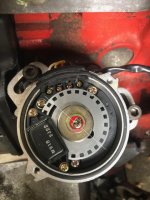
DSM CAS Slot Alignment.jpg
[picture credit to sideways242]

The pins from left to right when looking at the DSM CAS (not the harness connector) are:
4 - ground (black)
3 - +12v during run and start (red)
2 - crank signal (outer disc sensor, yellow)
1 - cam signal (inner disc sensor, white)


The DSM CAS crank and cam sensors are classified as "Hall Sensor - open collector" in the MS documentation. Both crank and cam need a pullup resistor (because they're open collector).

[Note: for added confusion, with MS2 and MS3base boxes, the crank sensor is connected to the MS VR or "universal" tach circuit and the cam sensor is connected to the MS Opto tach circuit. MS3X and MicroSquirt use two VR/Universal circuits. The sensor type may not match the circuit type.]

Find the exact instructions for your box here:
MS2V30_Hardware-3.4.pdf - see sections 5.2.3 (crank) and 5.2.14.2 (cam) or 5.2.14.4 (cam, alternate)
MS2V357_Hardware-3.4.pdf - see sections 5.2.3 (crank) and 5.2.14.2 (cam) or 5.2.14.4 (cam, alternate)
Microsquirt_Hardware-3.4.pdf - see section 5.2.3 (crank to VR1- and cam to VR2-, each with a 1K pullup to 5Vref added)
MS3baseV30_Hardware-1.5.pdf - see sections 5.2.3 (crank) and 5.2.14.2 (cam) or 5.2.14.4 (cam, alternate)
MS3baseV357_Hardware-1.5.pdf - see sections 5.2.3 (crank) and 5.2.14.2 (cam) or 5.2.14.4 (cam, alternate)
MS3XV30_Hardware-1.5.pdf - see sections 5.2.3 (crank) and 5.2.14.2 (cam)
MS3XV357_Hardware-1.5.pdf - see section s 5.2.3 (crank) and 5.2.14.2 (cam)

[Note: the disc shown in the MS Hardware Manuals in section ~6.9.12 "Mitsubishi CAS with aftermarket disc" is not the same as the Yoshifab disc, and uses a different MS configuration than shown here.]


Here's the starting TunerStudio setup for the DSM CAS (this one is for MS2V30 with the 5.2.14.2 cam setup). Other boxes will have a similar configuration.
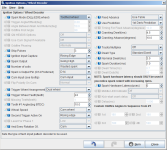
std dsm cas setup.png

If you run this setup with Fixed Advance on, and 10degrees Timing for Fixed Advance, a strobe light should show 10degrees timing during cranking/idle. If it's close, you can rotate the CAS to get to 10degrees. You can also change the Tooth #1 Angle in TunerStudio.

If the timing is way off (like 70deg BTDC), change the Second Trigger Active On edge, and try the timing light again.

If the timing is jumping a lot (+/- 30 deg) either at idle, or if you rev the engine while still in Fixed Advance mode, or between cranking and idle, you may need to change the Ignition Input Capture edge, and then re-adjust the tooth #1 angle.

Here's what a high speed logger - composite log should look like (with all noise filtering options turned off). Notice that the top cam edge (spike) is aligned inbetween the lower crank edges. If the cam signal is right on top of the crank signal, timing may jump. Changing the Ignition Input Capture edge should move this cam to crank alignment by half a tooth (~15degrees) and correct the alignment.
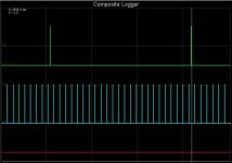
std dsm cas composite logger graph.JPG


Edit - here's what the waveforms on the bench look like with a Hantek 1008 oscilloscope and a MicroSquirt when setup for a DSM CAS
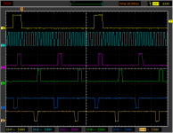
dsm_cas_wasted_spark_1200rpm_30deg_fixed_semi_seq.png

Top to bottom, the traces are:
- Cam sensor
- Crank sensor
- SparkA
- SparkB
- InjA
- InjB

Setup is:
- 1200 rpm
- Wasted Spark
- 10deg tooth #1 angle and Fixed 30deg advance
- 330cc injectors, semi-sequential injection, 75kPa

Here's the details showing the MS edge configuration and how Tooth #1 Angle is defined:
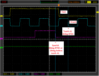
dsm_cas_wasted_spark_1200rpm_30deg_fixed2.png

The normal MegaSquirt/MicroSquirt circuits invert both the cam and crank signals. In the picture, the top cam signal drops as the big slot moves past the optical sensor. To reference off of the falling/trailing cam slot edge in TunerStudio, Second Trigger Active On is set to Rising Edge (due to the circuit inversion). The next Crank tooth edge defines the #1 Tooth position. To align on the falling Crank sensor signal, Ignition Capture is set to Rising edge (again due to the circuit inversion). Thus the first falling crank sensor edge after the falling cam sensor edge is Tooth #1. The Tooth #1 Angle setting in TunerStudio mechanically defines the tooth #1 position, 10deg BTDC in this example. OK so far?

This picture was taken with a 30deg fixed advance. The 3rd trace is the SparkA/IgnitionA signal. This example is setup to charge the coil(s) when high, which means the spark is generated when the signal drops low. With tooth #1 defined at 10deg BTDC, the falling SpkA edge for 30deg spark is 20deg before Tooth #1 or 20deg before falling crank edge. At 1200rpm, 20deg rotation is ~2.8ms, as marked by the vertical cursors.

Let me know if any of this doesn't make sense, or isn't working correctly, and we'll get it sorted out / better documented.

-Bob
 
Last edited:
I've spent a fair amount of time searching, unfortunately, the pictures of the head mounted CAS are long gone and so is the guy who did it. Does anyone have the pictures of the setup that they can share? I'm going to go to Megasquirt and don't want to run the block mounted setup, i don't feel like trying to source an idle shaft Are there other setups that have been used besides the DSM CAS? I remember years ago seeing someone had setup a trigger wheel on the balancer. Just looking for alternatives as it seems like the 60-2 setup can be finicky to use and maybe not the best for timing. Thanks
 
Okay, I'm going to pull the haven't-been-on-the-forum-in-years n00b card and ask a few questions here.

I'm using a CAS that has the plug instead of the wire lead, which appears to be different in orientation than the one pictured in post 208. This one has the gray/green metal hat vs. the black plastic one.

When I set the TDC mark on the underside, it places the inner slot fully underneath the sensor - regardless of orientation of the disc.

Now, this may not matter since I can rotate the CAS and/or set the advance in TunerStudio once it's running, but I'm curious if this is what others have seen with the plug type CAS.

Disclaimer: I have new Yoshifab disc on the way to replace the been-sitting-for-7-years surface rusted one.

<a data-flickr-embed="true" href="https://www.flickr.com/photos/33841570@N07/49968027902/in/album-72157714564591318/" title="Untitled"><img src="https://live.staticflickr.com/65535/49968027902_43cae60eb6_c.jpg" width="600" height="800" alt="Untitled"></a><script async src="//embedr.flickr.com/assets/client-code.js" charset="utf-8"></script>

<a data-flickr-embed="true" href="https://www.flickr.com/photos/33841570@N07/49967249178/in/album-72157714564591318/" title="Untitled"><img src="https://live.staticflickr.com/65535/49967249178_203ae07251_c.jpg" width="600" height="800" alt="Untitled"></a><script async src="//embedr.flickr.com/assets/client-code.js" charset="utf-8"></script>
 
Last edited:
It really doesn't matter where the slot is in relation to the sensor. Just adjust trigger angle with locked timing until you match the computer locked timing to what you see with a light.
 
It really doesn't matter where the slot is in relation to the sensor. Just adjust trigger angle with locked timing until you match the computer locked timing to what you see with a light.

Cool, thank you, that's where I was leaning from the research. Appreciate it, I've missed the support in this forum!
 
Try removing the yoshifab adapter, rotating the gear by one tooth and re-installing (equivalent to rotating a standard distributor drive gear by 1 tooth). It should then match the descriptions better.

While you can change the tooth#1 angle in TunerStudio to match however it's installed, it makes it a little easier for others to review your setup if you use the standard alignment.
 
So- we have a B20/30 setup CAS. I notice that the disc is opposite of the pic. line drawn from lower hole thru the center is LEFT of the inner slot. Can anyone confirm this is correct for the OHV engines?
appreciate any feedback from anyone who has done this install on OHV.
 
Back
Top