Yeah, my DCOE's are pretty much set it and (crowd joins in ) forget it. The few times it's started idling unevenly and I've started to mess with the carbs to fix it... it's ended up being something else. Cracked piston with low compression, or a flat cam lobe.
SU carbs always seemed to need a periodic session of tuning, they'd drift somehow., The DCOE's... just keep on doing the same thing.
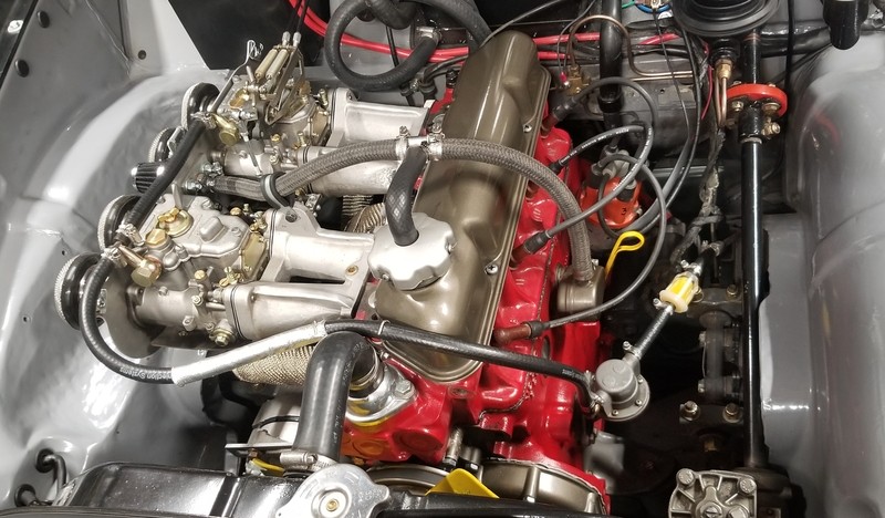
That said, and I am not familiar with that linkage setup at all, there are individual throttle stops/idle airflow adjusters on both carbs. Best seen in this pic:

The two screws on the inner sides of the carb, just below the throttle arms. And the little arm that reaches over from the front carb to the back carb looks like it had an adjustment on it.
EDIT: I marked up your pic a bit.
- idle mixture adjuster is circled in red - there are 4 of these, one on each carb barrel, adjust idle mixture for that cylinder only
- throttle stop/idle adjuster is circled in blue - there are two of these, one per carb, if the throttle linkage is slack with the pedal all the way up - these are the only things controlling the throttle position - and holding it slightly open to set the idle speed and front/rear balance
- throttle linkages have blue arrows pointing to them - these need to be adjusted to go slack when the pedal is all the way up. Just barely slack, you don't want much of a dead spot in the gas pedal travel before the slack is taken up. But a little slack is important so the throttle linkages is NOT holding the carb open slightly at idle, that needs to be done by the throttle stops.
So:
1) Linkage from the throttle cable to the front carb should go slack *just* before that carb hits it's own throttle stop. Adjust the length of that silver rod until it does that. That linkage needs to be slack so the throttle stop on the front carb is what dictates the idle position of the throttle.
2) Then, that adjuster on the cross-over connection to the rear carb needs to be adjusted so it goes slack right before idle as well, so the throttle stop on the rear carb is the only thing holding it open at that point.
Then, and only then, balance the air flow and set the idle speed using only those adjusters (and you may need to readjust the throttle linkages if needed if you close the carb enough and your slack disappears).
Once you have the airflow balanced front and rear, then start adjusting the idle mixture. This is exceedingly fiddly work. Everything else (compression, valve lash, spark plugs, ignition) has to be in great shape or you're wasting your time. I just methodically do one cylinder at a time. Turn the idle jet in 1/2 turn, wait a second or so to see if the motor runs better or worse. If worse, go back, and open it 1/2 a turn. When you hit the best setting (and it can be subtle), move on to the next carb, go down the line.
When you've set all the idle mixtures, you may need to reset the idle speed - if it was running crappy before it's probably idling higher now, so reset idle and rebalance front and rear. And then go through the idle adjustment spiel again, doing 1/4 turns. Turn it one way, wait a couple of seconds, listening carefully for the engine to either idle higher and/or run a bit more cleanly, or to do the opposite. Back and forth, up and down the line.
Hopefully on this pass, you barely made any changes, and you don't need to reset the idle or rebalance. If so, loop through it again. It's an iterative process between the idle air (throttle stops) and idle mixture and the idle speed. They all affect each other.
And if you're patient enough, you'll get a nice silky smooth and low idle. And be thankful you're not doing this on a V12 Ferrari with 6 twin-carbs, 12 idle mixture adjusters.
SU carbs always seemed to need a periodic session of tuning, they'd drift somehow., The DCOE's... just keep on doing the same thing.
That said, and I am not familiar with that linkage setup at all, there are individual throttle stops/idle airflow adjusters on both carbs. Best seen in this pic:
The two screws on the inner sides of the carb, just below the throttle arms. And the little arm that reaches over from the front carb to the back carb looks like it had an adjustment on it.
EDIT: I marked up your pic a bit.
- idle mixture adjuster is circled in red - there are 4 of these, one on each carb barrel, adjust idle mixture for that cylinder only
- throttle stop/idle adjuster is circled in blue - there are two of these, one per carb, if the throttle linkage is slack with the pedal all the way up - these are the only things controlling the throttle position - and holding it slightly open to set the idle speed and front/rear balance
- throttle linkages have blue arrows pointing to them - these need to be adjusted to go slack when the pedal is all the way up. Just barely slack, you don't want much of a dead spot in the gas pedal travel before the slack is taken up. But a little slack is important so the throttle linkages is NOT holding the carb open slightly at idle, that needs to be done by the throttle stops.
So:
1) Linkage from the throttle cable to the front carb should go slack *just* before that carb hits it's own throttle stop. Adjust the length of that silver rod until it does that. That linkage needs to be slack so the throttle stop on the front carb is what dictates the idle position of the throttle.
2) Then, that adjuster on the cross-over connection to the rear carb needs to be adjusted so it goes slack right before idle as well, so the throttle stop on the rear carb is the only thing holding it open at that point.
Then, and only then, balance the air flow and set the idle speed using only those adjusters (and you may need to readjust the throttle linkages if needed if you close the carb enough and your slack disappears).
Once you have the airflow balanced front and rear, then start adjusting the idle mixture. This is exceedingly fiddly work. Everything else (compression, valve lash, spark plugs, ignition) has to be in great shape or you're wasting your time. I just methodically do one cylinder at a time. Turn the idle jet in 1/2 turn, wait a second or so to see if the motor runs better or worse. If worse, go back, and open it 1/2 a turn. When you hit the best setting (and it can be subtle), move on to the next carb, go down the line.
When you've set all the idle mixtures, you may need to reset the idle speed - if it was running crappy before it's probably idling higher now, so reset idle and rebalance front and rear. And then go through the idle adjustment spiel again, doing 1/4 turns. Turn it one way, wait a couple of seconds, listening carefully for the engine to either idle higher and/or run a bit more cleanly, or to do the opposite. Back and forth, up and down the line.
Hopefully on this pass, you barely made any changes, and you don't need to reset the idle or rebalance. If so, loop through it again. It's an iterative process between the idle air (throttle stops) and idle mixture and the idle speed. They all affect each other.
And if you're patient enough, you'll get a nice silky smooth and low idle. And be thankful you're not doing this on a V12 Ferrari with 6 twin-carbs, 12 idle mixture adjusters.
Last edited: