• Hello Guest, welcome to the initial stages of our new platform!
    You can find some additional information about where we are in the process of migrating the board and setting up our new software here

    Thank you for being a part of our community!

B20 Fuel Injection Questions

New question...
I''m running the Megasquirt with direct coil control.
This requires that the distributor to be re-phased.
In my quest for easy return to stock, would it be advisable and strong enough if I were to cut the head off of the distributor rotor and reattach it about 25 or so degrees retarded? I was thinking JB Weld .
Instead of locking the distributor advance, I could set Megasquirt at fixed timing and use the centrifugal advance. I realize this removes a lot of flexibility, but I could switch back to carbs by just pulling the MS fuse, re-routing a couple of wires, the fuel pump, reinstall a stock rotor, reset the timing and drive away.
Feedback???

Thanks,
TR
 
Just pull the dist drive gear and clock that however you want. No need to chop up the distributor.

And it should be a fairly trivial task to lock the mechanical advance in a distributor. It's just little weighted levers and springs.

I'm curious to see how well the 'phantom SU carbs' fuel injection will work. In my mind, one of the main issues with that is the uneven cylinder pairing provided by the stock manifold. The firing order is 1342, so you can see that 1 and 2 are right next to each other, and so are 3 and 4. Not much of a problem on a carb that just adds fuel to whatever air flows through it. But it might be an issue with one injector squirting fuel into a shared port that has 180 degrees of rotation wait for one cylinder (3 and 2) and 540 degrees of wait time for the other two (4 and 1).

Probably less of an issue at higher RPMs? I know ye olde Bosch D-jet fires the port injectors in pairs, and the much newer LH on the 240's fires all 4 of them all at the same time - but in those cases, the fuel just has very slightly different amounts of 'loiter' time in their own individual intake runners and it's not like one cylinder has a chance to snag the fuel from the other.
 
You can't just rotate the distributor to phase it. The angle between the points and the plug contacts need to be changed. I already have a locked and phased distributor, just wondering about options.
The firing order may be a problem. I've got the injectors set up for four squirts per cycle which may spread out the injection time enough to help.
I've also seen a set-up where the injector is mounted in the air cleaner. Don't think I like that idea very much though.
 
Are you using the Bosch BIP 373 mounted on the MS2 board for coil control? If so, maybe gets somebody to poke you in the eye with a pointy stick now because that will tend to blunt the future pain of using the board mounted BIP. The board mounted BIP requires that you wire the primary circuit of the coil into the environment of the MS2 box. The coil primary circuit contains large amounts of harmonic currents and some rather nasty switching voltages. It will run; but, you risk generating controller resets and other undesirable mystery effects. Best to use a coil with an integrated driver or get an external driver for use with the coil.

Sawing off the top of the rotor and trying to glue it back together with the correct phasing does not seem like a winning solution. Also, there is absolutely no up-side to locking the timing in MS and using the distributors mechanical advance system. If you are going to do that just install a Pertronix module and have the timing controlled by the distributor and avoid the hassle of potential nasty currents in the MS2 box.

If you need 25 deg of retard on the trigger mechanism I suggest you try re clocking the breaker contact plate in the distributor body. On the non vacuum equipped distributor is the contact plate just retained by two screws through the body of the distributor??? If so, just drill two new holes at the appropriate angle to rotate the breaker plate. If you need to reverse everything, pull out the screws, rotate the breaker plate and un lock your advance mechanism. If you are looking for 25 deg of timing retard based upon crank angle, when drilling your holes just remember that is not distributor angle.

As a suggestion, your can do your additional wiring for coil control now; but, leave it unconnected. Get your MS up and running on just fuel first using the old points ignition. Once the fuel control is sorted and the engine is running, it will be easy to implement the coil control with the wiring in place. If you do both at the same time and the engine does not run, you have doubled the potential problem areas.
 
MS settings takes care of this for you.

First of all you must have a locked dist (welded or whatever)
You time the rotor so it is centered on the #1 post of the cap at 25?before, then lock down the distributor and don't move it EVER.
This centers the rotor to the post in the span of normal operation of 10? to 40? (25?mid point), this is setting the rotor phasing.
This is a one time mechanical adjustment and the distributor is not moved from this setting for any reason.

You use the "trigger angle offset" in TS and adjust the MS timing (using "fixed timing" of say "15?") so a timing light shows 15?.
While you have it in fixed mode rev the motor and verify the timing is rock steady, you can change the trigger edge or adjust for latency to dial this in if there is error.
NOTE: if the triggering edge is changed the trigger angle offset will have to be changed to correct the timing difference.
This aligns the MS to what you have in the table when you switch back to "use table".
Now a timing light is no longer needed and all running timing is set by the spark table in use.
 
^^^^ is where I was gonna go as well, works just fine without the need for crazy stuff. The trigger angle is designed for exactly what you're trying to do.

For the direct coil fire, I've been running mine like that for many years, in a wasted spark config using the Yoshifab CAS as a trigger, no issues whatsoever. I DID however have a ton of issues with feedback from the injector drivers once I added in the coil control, but a filter cap there and all was right with the world.
 
Last edited:
"Best to use a coil with an integrated driver or get an external driver for use with the coil."
Is this the Bosch 124 Power Stage?

"I DI however have a ton of issues with feedback from the injector drivers once I added in the coil control, but a filter cap there and all was right with the world."
Filter cap???

So much to learn.
Thanks,
TR
 
For the direct coil fire, I've been running mine like that for many years, in a wasted spark config using the Yoshifab CAS as a trigger, no issues whatsoever. I DID however have a ton of issues with feedback from the injector drivers once I added in the coil control, but a filter cap there and all was right with the world.

You can use the BIP373 drivers mounted on the heat sink in the MS2 case and it can work. You do need to need to be more careful with your wiring and grounding. The BIP373 grounds the coil through the V3.00 circuit board ground plane. If you have marginal solder connections or marginal grounding of the circuit board ground plane to the vehicle chassis the high transients in the coil primary current will show up as ground plane voltage transients causing problems for the processor.

If you are not careful with separation in the routing of the coil primary wire back into the MS2 box, the high current in the coil primary circuit can inductively couple into any circuit that is adjacent to it. This could include sensor circuits depending on whether you have or have no gone to the extra effort of twisted pairs and grounded shields.

As you have demonstrated, you can make this work. However, it is more problematic. There is a reason why, prior to the adoption of smart ignition coils just about every OEM used an ignitor / coil driver external to the ECU rather than install the drivers inside the ECU case.
 
MS settings takes care of this for you.

First of all you must have a locked dist (welded or whatever)
You time the rotor so it is centered on the #1 post of the cap at 25?before, then lock down the distributor and don't move it EVER.
This centers the rotor to the post in the span of normal operation of 10? to 40? (25?mid point), this is setting the rotor phasing.
This is a one time mechanical adjustment and the distributor is not moved from this setting for any reason.

You use the "trigger angle offset" in TS and adjust the MS timing (using "fixed timing" of say "15?") so a timing light shows 15?.
While you have it in fixed mode rev the motor and verify the timing is rock steady, you can change the trigger edge or adjust for latency to dial this in if there is error.
NOTE: if the triggering edge is changed the trigger angle offset will have to be changed to correct the timing difference.
This aligns the MS to what you have in the table when you switch back to "use table".
Now a timing light is no longer needed and all running timing is set by the spark table in use.

This can work; but, you don't know ahead of time where your trigger offset is going to end up. In section 6.2.1.1 of the MSExtra hardware manual, they cover the problems with phasing when using the existing points / sensor in the distributor for the trigger signal. They are clear that the desired trigger angle should be in the 60-90 deg BTDC range, or as an option in the case of a B18 / B20 you can go for 10 BTDC if that is what you are using for your cranking advance. They discuss the down sides to this.

If your method works out to a trigger angle in the 60 - 90 deg BDC range, then all is good. If you don't want to run your B18/B20 with more than 35 deg advance, then ending up with a trigger in the 45 - 90 deg range might also be acceptable.
 
Just pull the dist drive gear and clock that however you want. No need to chop up the distributor.

And it should be a fairly trivial task to lock the mechanical advance in a distributor. It's just little weighted levers and springs.

I'm curious to see how well the 'phantom SU carbs' fuel injection will work. In my mind, one of the main issues with that is the uneven cylinder pairing provided by the stock manifold. The firing order is 1342, so you can see that 1 and 2 are right next to each other, and so are 3 and 4. Not much of a problem on a carb that just adds fuel to whatever air flows through it. But it might be an issue with one injector squirting fuel into a shared port that has 180 degrees of rotation wait for one cylinder (3 and 2) and 540 degrees of wait time for the other two (4 and 1).

Probably less of an issue at higher RPMs? I know ye olde Bosch D-jet fires the port injectors in pairs, and the much newer LH on the 240's fires all 4 of them all at the same time - but in those cases, the fuel just has very slightly different amounts of 'loiter' time in their own individual intake runners and it's not like one cylinder has a chance to snag the fuel from the other.

You do raise a good issue. The 180 deg crank throws between 1 and 2 means that 1 is firing only 180 deg after 2 fires so the strategy of parking fuel in the manifold does not work so well. The 'phantom SU strategy' with the common 1&2 and 3&4 injectors is reminiscent of the siamesed intake ports used on the Mini A series and MG B series engines which also have the same 1342 firing order and crank throws as the B18 / B20 engines.

Section 4.1 of the MSExra Set up manual discusses the injector timing requirements for this type of siamesed port arrangement. The manual infers that this can be done with semi sequential injection without the use of a cam signal. Its not clear to me how that works unless they are presuming that you are using a crank wheel with a missing tooth. They don't get into that detail. I don't see how just a tach signal from a distributor will work because there is absolutely no information about which cylinder is firing.

Short answer, the siamesed intake arrangement that the OP is proposing to use can probably be made to work (they are making it work on Mini A and MGB engines). Its not something I needed to do so I didn't investigate the application; but, it is not clear to me that you can make this work without a cam or missing tooth signal. Before the OP gets too far down the road with hacking up his distributor he needs to investigate siamesed port operation because using the distributor to generate just a tach signal may be a dead horse.
 
I'm close to firing it up, just waiting for the surge tank. Speedpak from China is anything but speedy!
I'll give it a try and see how horrible it is. I've read about the theoretical problems of having adjacent cylinders firing, though no first hand experience.
If there is a problem with cylinders 4 & 1 running lean, I'll try something else.
I'm enjoying the feedback and am learning at the same time.
Thanks
TR

Here's what I found:
With semi-sequential, each injector channel will fire once per rev (twice per cycle) so you need to change to either 2 squirts/simultaneous or 4 squirts/alternating which would set the fueling correctly for that.

For semi-sequential, you only need a crank signal. Pair the injectors as you would the ignition coils for the wasted spark (cylinders 360 degrees apart).
 
Last edited:
For semi-sequential, you only need a crank signal. Pair the injectors as you would the ignition coils for the wasted spark (cylinders 360 degrees apart).

I am thinking crank signal implies a missing tooth wheel, not a tach signal. Also, you are not pairing the injectors on cylinders that are 360 deg apart. You are pairing 1 and 2 (3 and 4) which are 180 deg apart.

With 180 deg of spacing between 2 and 1, you have 540 deg of crank rotation to deliver fuel to cylinder 2 and only 180 deg to deliver to cylinder 1. That is ignoring all the complications / messiness associated with valve intake timing which exceeds 180 deg! You have to make sure that the 1 - 2 injector has adequate capacity to deliver fuel to cylinder #1 in 180 deg or less. If they don't allow you to set constraints, a lot of those on-line injector sizing calculators presume that you have up to a theoretical 720 deg of crank rotation to deliver fuel to one cylinder. Even the normally oversized (for a B20) Bosch 036 injector may not be adequate to deliver all the fuel required for one cylinder in less than 180 deg of crank rotation at 5000 - 6000 RPM.

As an additional observation, any injector that is large enough to deliver all of the fuel required for a single cylinder in less than 180 deg will likely be running at very small pulse widths at idle. You will need to select an injector that provides reliable operation at small pulse widths, otherwise you will likely never have a smooth idle. A lot of injectors don't provide consistent fuel delivery when the pulse width gets in the 1 - 1.5 millisecond range.

Using batch fire two squirts you should be able to get the engine to fire up, idle and perhaps run OK at low loads. Try some full load operation and you may risk melting cylinders 1 and 4. Because of the potentially extreme differences in the fuel mix going to the paired cylinders an O2 sensor will likely never give you an accurate picture of what is going on. Do your injector math before you try any full load operation.

I expect that there are close to 0 users on the Turbobricks forum who have tried the siamesed intake strategy so you are likely not going to get any prior experience to guide you here. Go to the Mini or MGB forums to look for set-up experience or consider getting injector bungs welded into each of your runners which would convert it to a more conventional 1 injector per port arrangement. Convert to conventional 1 injector per port and you will get lots of people offering opinions about operating issues on this forum.
 
Yep!
I've seen the light.
I'm still going to hook up the fuel and drive it around the block a few times and then go back to the drawing board on the intake and injector location.
I'm really looking for a TBI set up of some sort.
I'll post up when I come up with my next hair-brained idea.

Thanks for the education.

TR
 
You could also get an E/F head and use D-Jet injectors. No real need to use the D-Jet manifold along with that.

And I would be interested in seeing how the real world results are vs. the theory on the 'incorrectly' paired cylinders/ports puling from a common injector. In theory it sounds bad, but perhaps in reality it isn't?
 
That is what I'd do also, if I had a head with the injector ports. It looks like his project was to upgrade the injectors which required a new fuel rail. Looks like a nice job of doing it!
I'm trying to do this project with the existing head. I'm looking for a solution that can be used with the NA head and would also be applicable to a B18, which was never injected by Volvo.
 
Last edited:
you can always have injector bungs welded to the intake runners.

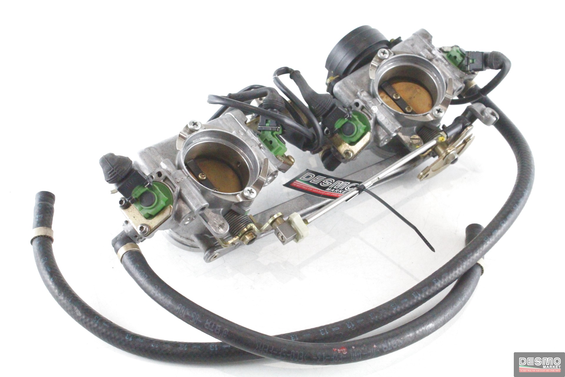
In the hopes of keeping it as a "easily returned to stock" kind of project. You might look into Ducati 996 throttle bodies. Each TB has 2 injectors. Looks like some mikuni style soft mounts and youd be set. Throat size is pretty damn close to SUs and they're not uncommon.

corpo-farfallato-doppio-iniettore-ducati-996-s-base_1.jpg
 
I've actually got a fuel rail project sitting on the bench right now, new custom rail, K-jet bosses rather than d-jet since they have the screw holes to use for holding the rail down, and some Hellcat injectors which are dirt cheap, #60, and have a projected tip that plays nicely with the boss/head setup. Really should turn out nice, but you do need the bosses.
 
Back
Top